3.4.7 Utilities and services
Utility routing can have a significant long-term impact on the future maintenance and street use. Poorly routed utilities can cause disruption, delay upgrades, and prevent maintenance and emergency access. Poor planning of diversions and connections can also lead to delays and excess costs for new development, and even prevent occupation of completed housing.
All services must be routed underground.
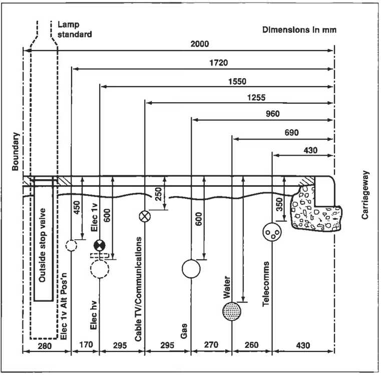
Services such as electricity, water, gas and telecommunications services must be grouped together in a minimum 2m wide strip, clearly marked on plans at the planning stage.
Service strip location will depend on the street typology and must be in one of the following locations:
- On Principal Streets (Type 1), Primary and Secondary Residential (Types 2.A and 2.B) the services must run under the footway.
- On mews (Type 3.A), a 2m strip must be designated. This must be 1.2m from the highway boundary to avoid blocking access to properties during maintenance.
- In lanes (Type 3.C), a 2m strip can run in the carriageway if the route is traffic free, or if alternative access is available.
Space must be provided for above ground infrastructure such as feeder pillars and cabinets to avoid street clutter. In all cases, minimum pavement widths must be maintained.
Utilities should not be routed beneath verges, as this will prevent the planting of trees and the construction of swales or rain gardens. Where they are routed beneath verges, seperate access strips must be provided alongside planting and SuDS features.
Utility Requirements for all Street Types
For each street typology, underground services shall be designed and laid in accordance with Appendix D (Public Utilities Services) of the Cheshire Design Aid. Reference shall be made to pages D7-D10 for guidance on service corridors, utility routing, easements, minimum cover depths, separation distances and preferred service locations within the highway corridor. Utility layouts should align with the standard service arrangement illustrated in Figure D1: Preferred Utility Layout and Service Depth Diagram (Appendix D, page D10), a copy of which is provided below, which identifies the preferred positioning of water, gas, electricity, telecommunications and cable services within verges and service strips.